
The Complete Guide to Pipeline and Flow-Line Construction in Nigeria’s Oil & Gas Industry
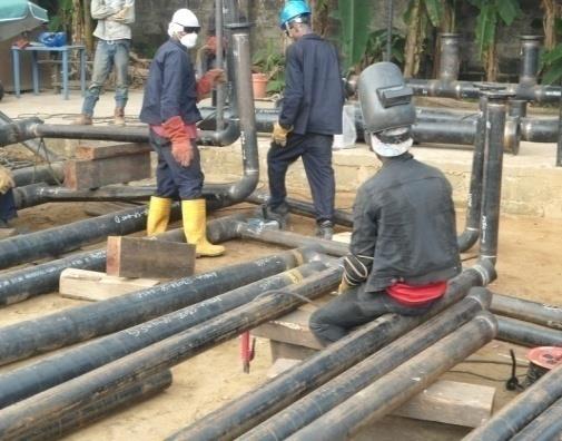 Pipeline welding and fabrication in progress on a CASIL project site.
Pipelines and flow-lines are the arteries of Nigeria’s oil and gas industry — moving crude, gas, and produced fluids from wellheads and flow stations to processing facilities, storage tanks, and export terminals. Built well, a pipeline can run safely for decades. Built poorly, or maintained carelessly, it becomes a source of leaks, spills, and shut-in production. This guide walks through what actually goes into pipeline and flow-line construction in the Niger Delta and onshore Nigeria more broadly, from route planning through to long-term integrity management — the way engineering teams on the ground approach it.
In This Guide
1. Design and Route Planning
Every pipeline project starts long before the first section of pipe is welded. Design and route planning set the boundaries within which everything else has to work, and mistakes made here are expensive — or impossible — to correct once construction is underway.
Route Selection
In the Niger Delta and other onshore Nigerian terrains, route selection has to balance several constraints at once: the shortest practical distance between origin and destination, the terrain (swamp, upland, creek crossings), proximity to communities and farmland, existing rights-of-way, and the location of other buried utilities or pipelines already in the corridor. A route survey typically combines desktop review of existing maps and satellite imagery with a physical walk-through of the proposed corridor, noting water crossings, road crossings, soil conditions, and any sensitive sites — mangroves, farmland under cultivation, or areas close to communities — that will need special design consideration or community engagement before work starts.
 A pipeline right-of-way being prepared prior to stringing and welding.
Pipe Sizing, Material Grade, and Wall Thickness
The pipe diameter and wall thickness are determined by the design flow rate, the operating pressure, and the properties of the fluid being carried — a sour crude or gas line with H2S content demands different material selection than a sweet crude line. Line pipe used in Nigerian oil and gas construction is typically specified to API 5L, with the grade (such as X42, X52, X60, or higher) chosen to balance strength against wall thickness and weight. Wall thickness is calculated to safely contain the design pressure with an appropriate safety margin, per the applicable design code, and corrosion allowance is added on top of the pressure-containment thickness for lines expected to see corrosive service over their design life.
Regulatory and Design Code Compliance
Pipeline design in Nigeria has to satisfy both international engineering codes and Nigerian regulatory requirements. Internationally recognized codes such as ASME B31.3 (Process Piping) or B31.4/B31.8 (Liquid/Gas Transportation Piping), and API 1104 for welding, generally form the technical design basis, while approvals and permits are obtained from the relevant Nigerian regulatory authorities — including the Nigerian Upstream Petroleum Regulatory Commission (NUPRC, the successor to DPR) for oil and gas facilities, and NESREA where environmental compliance is concerned. Right-of-way and way-leave agreements with landowners, communities, and other authorities (such as state ministries of works for road crossings) are secured before construction begins.
2. Procurement and Material Verification
A pipeline is only as reliable as the materials that go into it. Procurement is not simply a matter of ordering pipe and fittings — it is a verification exercise that continues from the moment materials arrive on site to the moment they are welded into the line.
- Mill Test Certificates (MTCs): Every batch of line pipe should arrive with mill certificates confirming chemical composition, mechanical properties, and that the material meets the specified API 5L grade. These are checked against the purchase order and project specification before the pipe is accepted onto site.
- Visual and dimensional inspection: Incoming pipe, fittings, valves, and flanges are visually inspected for transport damage, coating defects, and dimensional accuracy (outside diameter, wall thickness, out-of-roundness) before being released for construction.
- Fittings and valves: Elbows, tees, reducers, flanges, and valves are checked against the piping material specification (PMS) for the project to confirm pressure rating, material grade, and end preparation match what the design calls for.
- Consumables: Welding electrodes and filler wire are procured to match the approved welding procedure specification (WPS) and stored correctly — electrodes in particular are moisture-sensitive and are kept in heated storage ovens and issued through a controlled tracking system to avoid hydrogen-induced weld defects.
- Traceability: Each length of pipe is marked and logged so that its heat number and mill certificate can be traced back if a defect is later found — this traceability is what allows a root-cause investigation to isolate a bad batch rather than questioning the entire pipeline.
3. Construction: Stringing, Welding, and Coating
This is the stage most people picture when they think of pipeline construction — pipe going into the ground — but it is itself a sequence of distinct, carefully controlled activities.
Stringing
Pipe sections are transported along the cleared right-of-way and laid out (“strung”) end to end in the sequence they will be welded, following the pipe-laying schedule. In swamp and riverine sections of the Niger Delta, stringing often has to be done from barges or on timber matting laid over soft ground, since conventional truck access isn’t possible.
Alignment and Welding
Pipe ends are cleaned, beveled, and aligned using internal or external line-up clamps to achieve the correct root gap and alignment before welding starts — poor alignment at this stage is one of the most common causes of weld defects later found in radiography. Welding is carried out by qualified welders working to an approved Welding Procedure Specification (WPS), typically using a combination of processes such as Shielded Metal Arc Welding (SMAW), Gas Tungsten Arc Welding (GTAW) for the root pass, or semi-automatic welding for higher-productivity sections, in line with API 1104. Each welder must hold a current welder qualification certificate for the specific process, position, and pipe material being welded.
 Qualified welders work to an approved Welding Procedure Specification (WPS) on every joint.
Non-Destructive Testing (NDT)
Every girth weld is inspected before the line is allowed to proceed to coating and burial. The most common method is radiographic testing (RT), which produces an X-ray image of the weld that a qualified radiographer interprets against acceptance criteria in API 1104. Ultrasonic testing (UT), magnetic particle testing (MT), and dye penetrant testing (PT) are also used depending on the joint type and any surface-breaking defects suspected. Any weld that fails inspection is cut out and re-welded — it is not repaired in place unless the procedure specifically allows a qualified repair method.
Field Joint Coating
Line pipe usually arrives from the mill with a factory-applied external coating (commonly fusion-bonded epoxy or three-layer polyethylene/polypropylene) everywhere except the bare ends left for welding. After a girth weld passes inspection, the bare joint area is cleaned, sometimes grit-blasted, and coated in the field — using heat-shrink sleeves, liquid epoxy, or a comparable system — to restore full corrosion protection along the entire length of the line. Coating integrity is checked with a holiday (pinhole) detector before the pipe is lowered into the trench, since even a small coating defect becomes a corrosion initiation point once buried.
4. Trenching, Lowering-In, and Backfill
- Trench excavationTrenches are excavated to the depth and width specified in the design, accounting for the pipe diameter, required cover depth, and soil conditions. In swamp terrain, trenching is often done using long-reach excavators from floating plant or timber mats, and dewatering may be required to keep the trench workable.
- Trench base preparationThe trench bottom is checked for rocks, debris, or hard spots that could damage the coating, and a bed of sand or fine spoil is placed where the native soil is unsuitable for direct pipe contact.
- Lowering-inThe strung and coated pipe section is lifted using side-boom tractors or cranes working in coordinated tandem and lowered smoothly into the trench, avoiding sudden bending stress or coating damage against the trench walls.
- Padding and initial backfillA layer of clean sand or select fill is placed around and over the pipe before general backfill, cushioning the coating from sharp rock and stones in the native spoil.
- Final backfill and reinstatementThe trench is backfilled to grade, and the right-of-way is reinstated — cleared farmland is often re-graded and, where agreed with the community or landowner, made available for continued cultivation once the pipeline is safely buried at design depth.
- Water crossingsCreek and swamp crossings may require specialized methods such as horizontal directional drilling (HDD), wet crossing techniques, or additional concrete weight-coating to control pipe buoyancy in waterlogged trenches.
Why Cover Depth Matters
Minimum cover depth isn’t arbitrary — it protects the pipeline from surface loading, third-party excavation damage, and agricultural activity above it. Cover depth is checked and recorded at intervals along the line before backfill is signed off, and any location where design cover cannot be achieved is flagged for an engineering review rather than being backfilled as-is.
5. Hydrotesting and Tie-In
Before a pipeline is allowed to carry hydrocarbons, it has to prove it can safely contain pressure. This is done through hydrostatic testing: the completed line is filled with water (with air fully vented out), pressurized to a level above its normal operating pressure — typically defined by the design code and project specification — and held for a specified duration while pressure and temperature are continuously monitored for any drop that would indicate a leak.
A successful hydrotest is documented in a test certificate that becomes part of the pipeline’s permanent integrity record. If the line fails to hold pressure, the affected section is located, exposed, repaired or replaced, and the test is repeated until it passes. Once hydrotesting is complete, the test water is drained and disposed of responsibly, the line is dried (commonly by pigging with air or nitrogen), and the pipeline is connected — “tied in” — to existing infrastructure such as manifolds, flow stations, or export lines, with the tie-in welds receiving the same NDT scrutiny as every other joint on the line.
| Stage | Primary Purpose | Typical Check |
|---|---|---|
| Pre-commissioning cleaning | Remove mill scale, welding debris, and construction residue | Pigging with cleaning/gauging pigs |
| Hydrostatic test | Prove the line holds design pressure without leaking | Pressure hold over specified duration |
| Dewatering and drying | Remove test water before hydrocarbon introduction | Dew point / moisture measurement |
| Tie-in | Connect the new line to existing facilities | Weld NDT on tie-in joints |
6. HSE Throughout the Process
Pipeline construction combines several higher-risk activities at once — excavation, lifting, hot work, confined space entry at tie-in points, and work near live facilities — which is why Health, Safety, and Environment management is not a separate phase but runs continuously through every stage described above.
A Job Hazard Analysis (JHA) is carried out for each distinct task before work starts, identifying the specific hazards involved and the controls required — from permit-to-work requirements for hot work and excavation, to exclusion zones around lifting operations, to gas testing before any confined-space entry at tie-in points. Personnel working on pipeline construction sites wear PPE appropriate to the task, including flame-resistant coveralls for welding and hot work, hearing and eye protection, and appropriate footwear for wet or uneven terrain.
 HSE inspection and permit-to-work checks accompany every stage of pipeline construction.
Environmental protection is a parallel concern, particularly in the ecologically sensitive Niger Delta — spill prevention measures, secondary containment for fuel and chemical storage on site, and controlled disposal of hydrotest water and waste materials are planned into the work rather than treated as an afterthought. This mirrors the CASHES framework — Community Affairs, Safety, Health, Environment, and Security — that guides HSE practice on projects of this kind, and which we’ve written about in more depth in our CASHES framework guide.
7. Long-Term Maintenance and Rehabilitation
Commissioning a pipeline is the start of its service life, not the end of the engineering work. A well-built line still needs ongoing integrity management to keep operating safely for its intended design life, which for many onshore pipelines is measured in decades.
Routine Integrity Monitoring
Cathodic protection systems, applied to buried steel pipelines to control external corrosion, are checked at regular intervals to confirm the pipe is being adequately protected. Right-of-way surveillance — whether on foot, by vehicle, or by aerial patrol — watches for third-party encroachment, illegal tapping (a significant risk factor in parts of the Niger Delta), erosion exposing the pipeline, or vegetation and construction activity that could threaten the line.
In-Line Inspection and Pigging
Where the pipeline design allows it, intelligent pigging — running an instrumented inspection tool through the line — can detect internal and external corrosion, dents, and other wall anomalies without excavation, allowing operators to prioritize repairs based on actual condition data rather than assumption.
Repair and Rehabilitation
When inspection or a reported incident identifies a defect, repair options range from a full spool replacement, to welded sleeve repairs, to composite wrap repairs for certain types of external damage — the appropriate method depends on the defect type, severity, and the applicable repair code. Any repair follows the same rigor as new construction: a qualified procedure, qualified welders where welding is involved, and NDT verification before the line is returned to service.
The Bottom Line
A pipeline’s integrity is decided long before it’s ever put into service — in the quality of the route survey, the discipline of material verification, the skill of the welders, and the thoroughness of the hydrotest. Maintenance afterward manages the pipeline’s condition; it can’t make up for shortcuts taken during construction.
Planning a Pipeline or Flow-Line Project?
CASIL’s engineering team handles pipeline and flow-line construction from route survey through hydrotest and tie-in, with HSE built into every stage. Talk to us about your project scope.